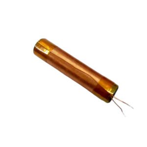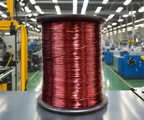
Ferrite rod inductor coils serve various purposes. They are made by winding conductive materials around a magnetic core, with copper wire being the most representative example. The magnetic core can be removed or replaced with ferromagnetic materials. Materials with higher permeability than air can confine the electromagnetic field more tightly around the inductor element, thereby increasing the inductance.

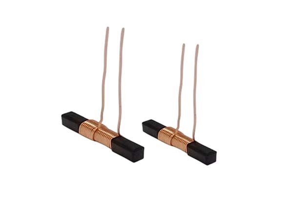
There are many types of inductors, most of which are made by winding enamel-coated wire around ferrite cores. Some protective inductors completely encase the ferrite rod inductor coil within the ferrite material.
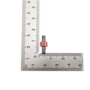
Certain inductive elements have adjustable cores, allowing for changes in inductance. Small inductors can be directly etched onto PCB boards in a spiral path. Low-value inductors can also be manufactured using similar techniques as those used for transistors in integrated circuits, where aluminum interconnects are often used as the conductive material.
Regardless of the method used, the most commonly constrained application is known as the “rotor” circuit, which demonstrates similar performance to inductive elements using a capacitor and active components. For high-frequency isolation, inductive elements typically consist of a metal wire passing through a magnetic core or bead.
When alternating current (AC) flows through the ferrite rod inductor coil, it generates a changing magnetic flux around the wire. The magnetic flux linked to the current generating it creates a relationship. When direct current (DC) flows through the inductor, it exhibits a fixed magnetic field that does not change over time.
However, when AC flows through the inductor, the magnetic field changes over time. According to Faraday’s law of electromagnetic induction, the changing magnetic field induces an electromotive force (EMF) across the coil, effectively acting like a “new power source.” When a closed circuit is formed, this induced EMF generates an induced current. According to Lenz’s law, the total magnetic field generated by the induced current attempts to oppose the change in magnetic flux.
Winding Methods for Ferrite Rod Inductor Coils
When winding ferrite rod inductor coils, several important factors need to be considered, especially since many inductor coils are non-standard components tailored for specific needs. Here are a few aspects to keep in mind during the winding process:
1.Choose the Winding Method According to Circuit Requirements:
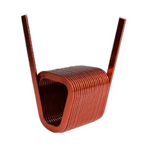
- For air-core inductor coils, the winding method should be determined based on circuit requirements, the desired inductance value, and the diameter of the coil framework. The interleaved winding method is suitable for high-frequency and ultra-high-frequency circuits. When the number of turns is less than 3 to 5, a framework may not be necessary, resulting in strong performance with a Q factor between 150 and 400, as well as excellent stability. Single-layer tightly-wound coils are more appropriate for shortwave and medium-wave circuits, with a Q factor reaching 150 to 250 and high stability.
2.Ensure the Coil's Current Carrying Capacity and Mechanical Strength:
- It is not recommended to use excessively thin wire for winding ferrite rod inductors, as this may increase resistance and lower the Q factor. Thinner wires have lower current carrying capacity and mechanical strength, making them more susceptible to breakage. Therefore, it is essential to select appropriate wire for winding while ensuring both the coil’s current carrying capacity and mechanical strength.
Need a customized coil?
Our experts for coils manufacturing will be pleased to advise you.